Add RODI Filter
Having a RODI Water Filtration System is crucial for a reef tank. It enables you to produce water that is free from undesirable chemicals and elements. An effective RODI filter guarantees that you do not introduce any hazardous chemicals from your city’s water filtration plant into your aquarium. Additionally, it ensures that all non-toxic phosphates and silicates are eliminated from the water to prevent the growth of algae.
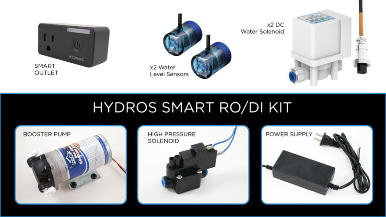
Here is what you’ll need to get started:
- Two water sensors are installed and ready to go.
TIP: If you still need to configure your water sensor input, please follow the instructions
here.
- Two water solenoids are connected to the HYDROS control but not configured. We will do that later.
- A Booster Pump with a high-pressure solenoid incorporated
Step 1: Install the Hardware
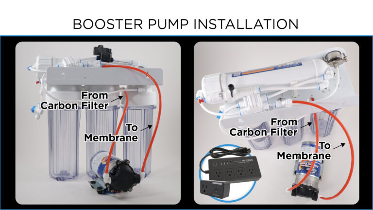
- Install the Booster pump on your RODI unit – Place the booster pump between the Carbon prefilter and your RO membrane. It will require you to cut the line to attach the booster pump.
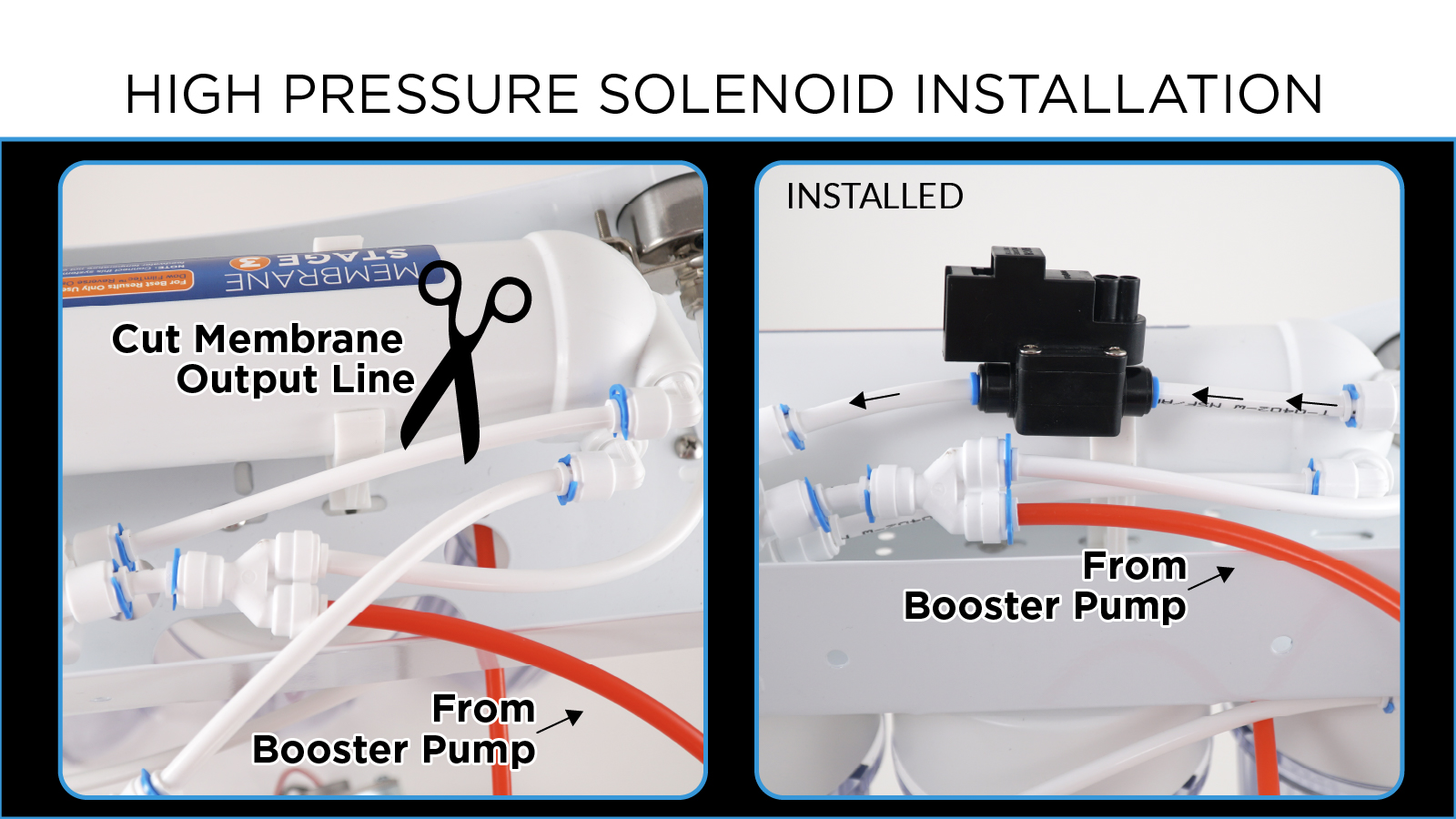
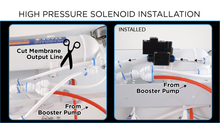
- Install the High-Pressure Switch – Cut the line from the RO membrane and install the switch. Pay attention to the directional arrow on the high-pressure switch!
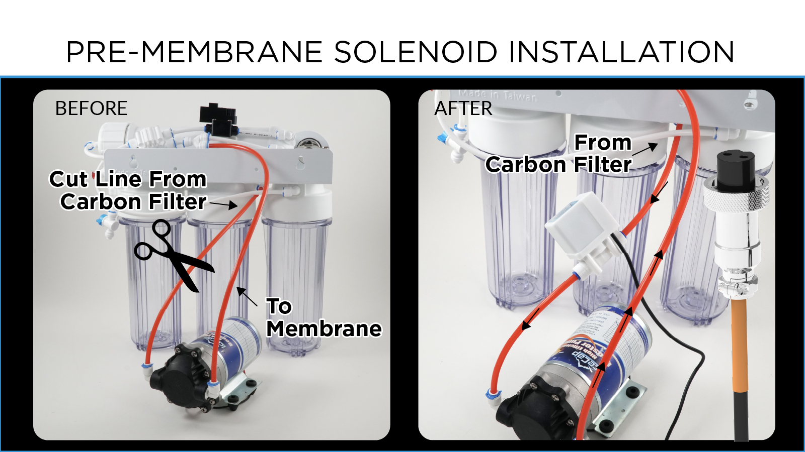
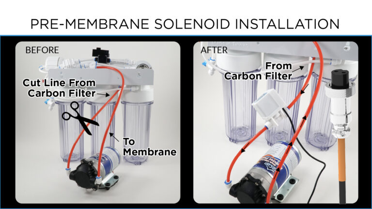
- Install Feed Input Solenoid – Place the solenoid on the line between the Carbon prefilter and your Booster pump. Pay attention to the directional arrow on the solenoid!
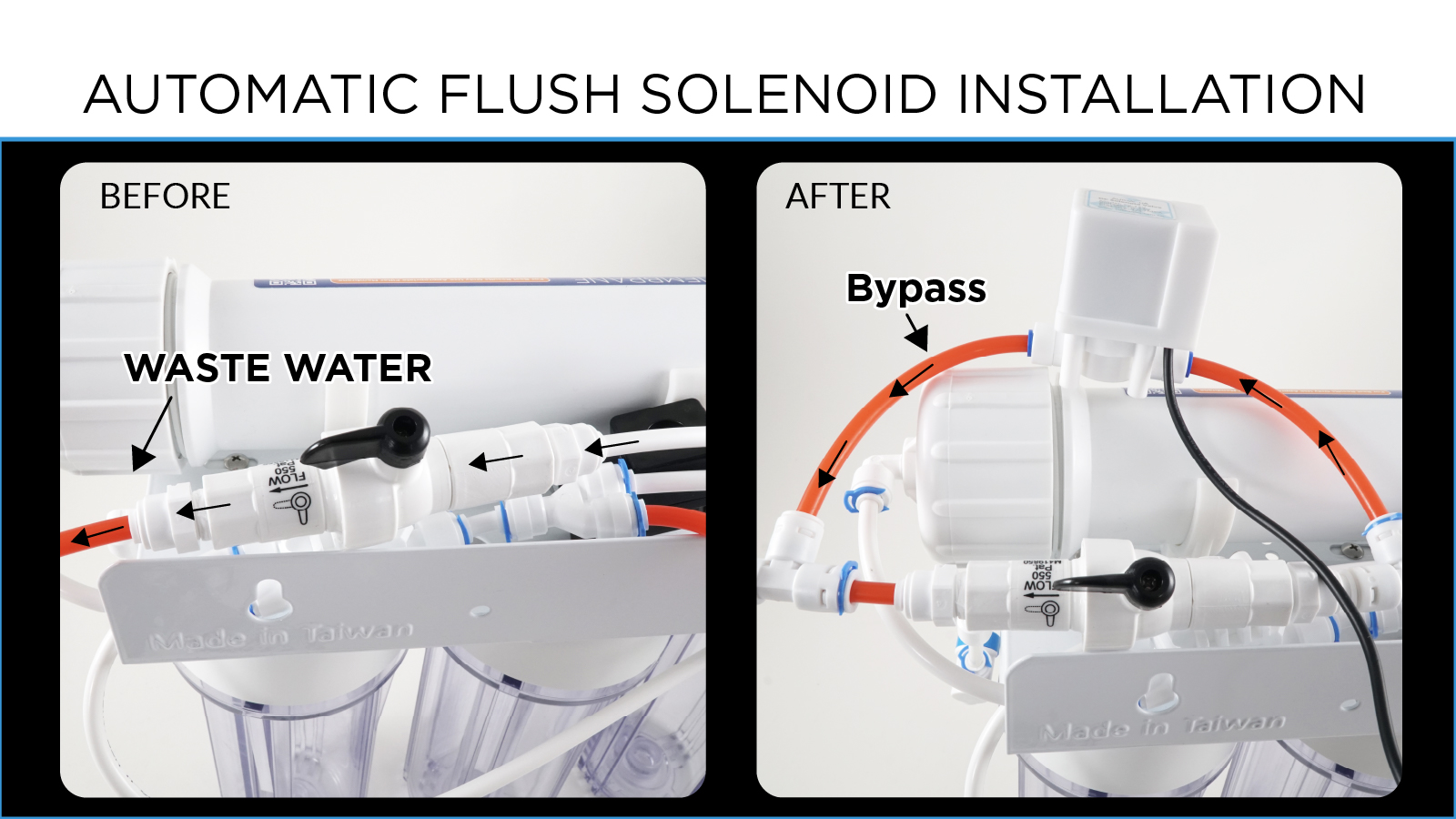
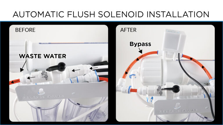
- Install Flushing Solenoid – You must create a bypass around the restrictor. First, cut the line before and after the restrictor and install the “Tee” fittings. Then, attach a line from one “Tee” fitting to the other to create the bypass. Finally, cut the bypass line and install the Flush solenoid. As before, pay attention to the flow-direction arrows before you install the solenoid!
Step 2: Create the RODI Output
- From the STATUS screen on your HYDROS app, top on the three horizontal dots to the right of the OUTPUTS label and select “Add / Edit Output.”
- Tap on the + symbol at the bottom right of the page
- Type in the name of your new output and then tap “Create.”
Step 3: Configure your RODI
- Family: RODI
- Feed Output Device: Your solenoid is installed on your RODI before your RO membrane filter INPUT. Here, you tell the controller where that solenoid’s power is connected.
- Power Safe Range: You can specify an “acceptable” power use range. If power consumption is outside the range, a notification will trigger if selected.
WARNING: This option is NOT available if the “Feed Output Device” is assigned to an outlet that cannot monitor power, such as a WiFi Strip outlet.
- Power Notification Level: You can select the notification level that triggers if the power consumption falls outside the “Power Safe Range.”
WARNING: This option is NOT available if the “Feed Output Device” is assigned to an outlet that cannot monitor power, such as a WiFi Strip outlet.
- Enable Advanced Settings: If you are an expert, you can customize the default output settings to suit your system better.
- Flush Output Device: This solenoid is installed on your RODI’s restrictor bypass. Your HYDROS will open and close this solenoid to bypass the restrictor and allow the RODI unit to flush the unit.
The HYDROS will automatically flush the RODI:
- Immediately after turning on the RODI unit, the flush solenoid will be open for 60 seconds.
- After running every hour, the control will flush the RODI unit for 60 seconds.
- Power Safe Range: You can specify an “acceptable” power use range. If power consumption is outside the range, a notification will trigger if selected.
WARNING: This option is NOT available if the “Flush Output Device” is assigned to an outlet that cannot monitor power, such as a WiFi Strip outlet.
- Power Notification Level: You can select the notification level that triggers if the power consumption falls outside the “Power Safe Range.”
WARNING: This option is NOT available if the “Flush Output Device” is assigned to an outlet that cannot monitor power, such as a WiFi Strip outlet.
- Enable Advanced Settings: If you are an expert, you can customize the default output settings to suit your system better.
- Boost Output Device: This is the outlet to which your booster pump is connected.
- Power Safe Range: You can specify an “acceptable” power use range. If power consumption is outside the range, a notification will trigger if selected.
WARNING: This option is NOT available if the “Boost Output Device” is assigned to an outlet that cannot monitor power, such as a WiFi Strip outlet.
- Power Notification Level: You can select the notification level that triggers if the power consumption falls outside the “Power Safe Range.”
WARNING: This option is NOT available if the “Boost Output Device” is assigned to an outlet that cannot monitor power, such as a WiFi Strip outlet.
- Enable Advanced Settings: If you are an expert, you can customize the default output settings to suit your system better.
- High-Level Input: Here, you select the Water Sensor input for the water sensor near the top waterline of your freshwater reservoir.
TIP: To see a list of all inputs available on MULTIPLE devices, you must first
create a Collective. Otherwise, only inputs on the same device will show.
- Low-Level Input: You select the Water Sensor input for the water sensor near the bottom of your freshwater reservoir.
TIP: To see a list of all inputs available on MULTIPLE devices, you must first
create a Collective. Otherwise, only inputs on the same device will show.
- Leak Detector Input: If you have a leak detector near your RODI unit, this is where you specify the Sense Port location.
TIP: To see a list of all inputs available on MULTIPLE devices, you must first
create a Collective. Otherwise, only inputs on the same device will show.
- Schedule: You can create a simple or complex schedule to run the output.
- Start Time: This is when the first test will become active.
- End Time: This is the time when the testing ends.
- Enable Advanced Settings: If you are an expert, you can customize the default output settings to suit your system better.
- Active Modes: This allows you to select which modes this output will be operational in and which modes should be turned off.
- Depends On: This feature allows you to turn the output based on the status of another output. To enable this, select it from the list of available outputs.
- Dependency Mode: You can turn the output ON or OFF based on the other output.
- OFF if OFF: Will turn the current output OFF if the output it depends on is OFF.
- OFF if ON: Will turn the current output OFF when the output it depends on is ON.
- ON if OFF: Will turn the current output ON when the output it depends on is OFF.
- ON if ON: Will turn the current output ON when the output it depends on is ON.
- Is Invisible: If you choose to hide the input from the status screen, it will only become visible on pages that have “Show Invisible” selected.
Step 4: Save
- After configuring the output, tap the yellow bar at the bottom to upload your changes to the cloud and each HYDROS device.
Rename Output & Change Icon
- From the STATUS screen, tap on the Output you wish to modify.
- On the popup, tap on the “Gear” icon on the bottom right.
- From the Output setup page, tap on the “Pencil” icon on the top left.
- Type in the new name you wish
- If you wish to change the default icon, tap “Change Icon.”